By now you should have installed Code Composer Studio* and the USB drivers that came with it. The USB drivers let us download to the flash ROM in the microcontroller and also let us talk to the chip from a terminal window. More about that later.
Let’s start with the simplest of applications, a blinking lights demo. That’s embedded programming’s version of “Hello World”. The LaunchPad has two LEDs we can control, conveniently colored red and green. All we need to figure out is how to write to the output pins connected to the LEDs and some kind of delay mechanism to slow down the blink rate to human speeds. Simple enough.
Hop over to TI’s Code Example page and grab the zip file for your particular processor. For those of us using the ‘2553 chip that would be at MSP430G2xx3. Unzip it in a convenient location and pull out this file: msp430g2xx3_1.c. Copy it to your EW project directory. In EW, right-click on the project name and add the new file to the project. Double-click it to open it in the source code window. The code should look like this:
//**************************************************************
//  MSP430G2xx3 Demo - Software Toggle P1.0
//
//  Description; Toggle an LED by xor'ing P1.0 in software.
//  ACLK = n/a, MCLK = SMCLK = default DCO
//
//                MSP430G2xx3
//             -----------------
//         /|\|              XIN|-
//          | |                 |
//          --|RST          XOUT|-
//            |                 |
//            |             P1.0|-->LED
//
//  Originally by D. Dang
//  Texas Instruments, Inc
//  December 2010
//  Built with CCS Version 4.2.0, etc.
//**************************************************************
#include  <msp430g2553.h>

void main(void)
{
    // Stop the watchdog timer.
    WDTCTL = WDTPW + WDTHOLD;

    // Set P1.0 direction to output.
    P1DIR |= 0x01;

    while (1)
    {
        volatile unsigned int i;

        // Toggle P1.0 using exclusive OR.
        P1OUT ^= 0x01;

        // Delay
        for (i = 50000; i != 0; i--)
        { }
    }
}
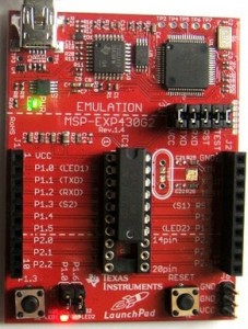
 Look at the comment block at the top of the file. Every source file should have a comment block like this explaining the purpose of the file and details that help the programmer understand how it all fits together. TI’s examples include a little textual block diagram. This example shows the reset button and LED output. P1.0 is shorthand for Port 1, Pin 0. If you read the silkscreen on the LaunchPad, you will see “P1.0” above the red LED at the bottom of the board, above a black jumper. Leave the jumper installed in order to turn on the LED. Also notice “P1.6” above the green LED on the right. Ignore the XIN and XOUT pins for now. Those pins connect to an optional watch crystal.
#include <msp430g2553.h>
Now let’s pick the program apart. The first line below the comment block is an “include” compiler directive. Compiler directives don’t generate machine code, but they tell the compiler to take notice and do something. In this case, the compiler will read the contents of file “msp430g2553.h” and insert it here before continuing on. The “.h” suffix on the file name indicates a C header file. Header files typically contain definitions and references to exteral functions, that is, functions defined in a corresponding “.c” file.
void main(void)
Next we come to the main program function, which in most cases is creatively named “main”. The voids indicate that main returns nothing when it finishes (the left “void”) and takes no parameters (“void” parameter list in parentheses).
void main(void)
{
    // Stop the watchdog timer.
    WDTCTL = WDTPW + WDTHOLD;
  ...
}
 C is a block structured language. Related sections of code are grouped into blocks surrounded by curly braces. Executable statements that do the work are in the main program block. The very first step in an embedded program is usually to turn off the watchdog timer (WDT) so it won’t interfere with initial configuration of the hardware. WDT serves as a dead-man’s stick, resetting the microcontroller unless the program resets the WDT before it expires. It’s a last resort for the program to repair itself when it goes off into the weeds. Because demo programs are not mission critical, they usually run with WDT turned off.
 You might be wondering exactly how that line works. WDCTL is the control register for the watchdog timer. WDTPW is ?. We add WDTHOLD which is the WDT hold bit, turning that bit on in the control register. Look at the register diagram on page in the MSP430G2xx2 User’s Guide. It shows the bit positions for WDTP and WDTHOLD within the WDCTL control register. [TODO: research this.}
*NOTE: IAR Embedded Workbench is a bit slicker than Code Composer Studio, in my opinion, BUT after a few weeks I hit the 4K code limit. I copied my source code into a CCS project and haven’t looked back.
[TODO – add procecure for compiling and running the demo. Follow along the steps in CCS to get it right.]


 Have you ordered that LaunchPad yet? While you’re waiting on it, see if you can install the IDE and get it working. You’ll want to set it up for the MSP430G2553 target, and select the simulator option for now, rather than the actual hardware. Create a project and experiment.